Articles By Our Members
"Simple And Crude" Brass Propellers
by Bob Warburton, May 2005
For those who have a talent for soldering and metal handiwork, here is a
technique I have used to make brass propellers for my models. The results
are good solid basic propellers, the quality of which is determined by the
care taken in the fabrication. My results have ranged from good enough for
test purposes, to near commercial quality. As usual, for any project, the
"devil is in the detail". Sorry about the photo quality, it was a last
minute decision to document this particular propeller. The text is the most
important part anyway. (That's my excuse and I'm sticking to it).
Decide upon the design and size of your propeller. You need to choose
the number of blades, diameter, hub size and shape, shaft size, shaft
attachment, pitch etc.
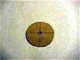 Make a circular template for the blade radial spacing; this will help you to
mark the hub. This one is for a four-blade model. You can make blade
templates as well if necessary; this one didn't need it, as they were
trimmed quarter circles.
Make a circular template for the blade radial spacing; this will help you to
mark the hub. This one is for a four-blade model. You can make blade
templates as well if necessary; this one didn't need it, as they were
trimmed quarter circles.
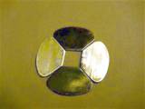 You will need to cut the blades out of brass sheet stock; I use aviation
snips after tracing a pattern with a permanent fine tip marker. I use .040
brass, it is sturdy enough for most props. These blades are for an
"aggressive" prop. It will be slow turning and is symmetrical for powerful
thrust in either direction (tugboat application). Note the slightly used
blades... That's what comes from not being quite accurate enough with
cutting the slits the first time around. Clean the blades with emery or a
scotchbrite pad before assembly.
You will need to cut the blades out of brass sheet stock; I use aviation
snips after tracing a pattern with a permanent fine tip marker. I use .040
brass, it is sturdy enough for most props. These blades are for an
"aggressive" prop. It will be slow turning and is symmetrical for powerful
thrust in either direction (tugboat application). Note the slightly used
blades... That's what comes from not being quite accurate enough with
cutting the slits the first time around. Clean the blades with emery or a
scotchbrite pad before assembly.
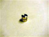
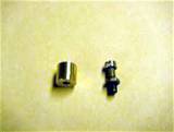 Machine the hub, on a lathe preferably, smaller ones can be done with an
electric drill, but I don't recommend it for the faint of heart. Perhaps a
friend with a lathe can be called upon to help. Clean the hub also before
assembly.
Machine the hub, on a lathe preferably, smaller ones can be done with an
electric drill, but I don't recommend it for the faint of heart. Perhaps a
friend with a lathe can be called upon to help. Clean the hub also before
assembly.
 You should have a mount for the hub to hold the hub and blade assembly for
soldering; this is a machine screw with locknut in this case. Attach the
template to the hub and mark the blade radial centerlines with the marker.
I find it much preferable to pencil, which rubs off easily.
You should have a mount for the hub to hold the hub and blade assembly for
soldering; this is a machine screw with locknut in this case. Attach the
template to the hub and mark the blade radial centerlines with the marker.
I find it much preferable to pencil, which rubs off easily.
 Remove the template, and extend the markings for the radial centerlines all
the way across the hub where the slit for the blades will be located.
Remove the template, and extend the markings for the radial centerlines all
the way across the hub where the slit for the blades will be located.
Mark the circumferential center of the slits with a line all the way
around the hub; this is the starting point for the hacksaw cut. Accuracy is
important in these steps, as it determines symmetry and balance. Rubbing
alcohol on a "q-tip" is a good eraser.
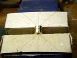 I have marked cardboard jaw liners (helps to eliminate scratching) for the
vise with a centerline and a pair of angle markings for the blade pitch;
these will be used as guides when cutting the slits with a hacksaw.
I have marked cardboard jaw liners (helps to eliminate scratching) for the
vise with a centerline and a pair of angle markings for the blade pitch;
these will be used as guides when cutting the slits with a hacksaw.
I use a fine hacksaw blade, about 32-36 t.p.i. since it suits the .040"
blades.
 Place the hub in the vise on the centerline and do a very small and gentle
"back cut" at the intersection of the radial and circumferential centerlines
to verify the starting position of the slit. -- About two more strokes and
the hub is either on the way to being correct or ruined.
Place the hub in the vise on the centerline and do a very small and gentle
"back cut" at the intersection of the radial and circumferential centerlines
to verify the starting position of the slit. -- About two more strokes and
the hub is either on the way to being correct or ruined.
 Realign if necessary and finish the cut to the required depth, keeping the
bottom flat and the sides smooth by maintaining accurate blade positioning.
Use the guidelines on the vise jaw liners to keep the saw aligned; there
will be one on each side of the blade. Repeat this two-step cutting
procedure for the other blade slots.
Realign if necessary and finish the cut to the required depth, keeping the
bottom flat and the sides smooth by maintaining accurate blade positioning.
Use the guidelines on the vise jaw liners to keep the saw aligned; there
will be one on each side of the blade. Repeat this two-step cutting
procedure for the other blade slots.
Clean the marker lines off the hub with rubbing alcohol. You can try a
test fit of your blade templates (if you made them) at this point to get an
idea how things line up.
 Tap the blades into the slots gently. If the blade is too tight to fit, a
different hacksaw blade should be used, the roughness of the hacksaw cut
should provide all the space required for solder wicking. If it is a little
too loose, you can dimple it slightly with a center punch or put in a little
wrinkle at the very bottom to hold it in place. Do not have a very large
gap, ordinary (60-40) solder is strong for shear force in a thin film, but
not if too thick.
Tap the blades into the slots gently. If the blade is too tight to fit, a
different hacksaw blade should be used, the roughness of the hacksaw cut
should provide all the space required for solder wicking. If it is a little
too loose, you can dimple it slightly with a center punch or put in a little
wrinkle at the very bottom to hold it in place. Do not have a very large
gap, ordinary (60-40) solder is strong for shear force in a thin film, but
not if too thick.
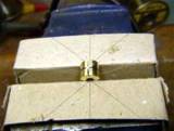
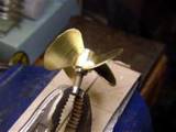 Mount the hub and blade assembly to your "hub holder". Grip with a pair of
vise grips, and you are ready to start soldering. I find that this method
gives you the most control over application of solder and heat. I use a
mini piezo ignition butane powered torch. Be careful of the back flow of
heat to the tip caused by getting too close to the work as they seem to have
an auto shutdown feature.
Mount the hub and blade assembly to your "hub holder". Grip with a pair of
vise grips, and you are ready to start soldering. I find that this method
gives you the most control over application of solder and heat. I use a
mini piezo ignition butane powered torch. Be careful of the back flow of
heat to the tip caused by getting too close to the work as they seem to have
an auto shutdown feature.
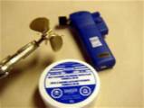 I use a paste flux applied to a warmed assembly for cleaning as it
penetrates the gaps well and does a thorough cleaning. I am using 60-40
resin core solder. I have found it to be totally adequate for strength (see
#13 above).
I use a paste flux applied to a warmed assembly for cleaning as it
penetrates the gaps well and does a thorough cleaning. I am using 60-40
resin core solder. I have found it to be totally adequate for strength (see
#13 above).
Here is where your soldering skill is tested. Use just enough heat to
melt the solder. Work around the assembly finishing the soldering of one
blade at a time. Do not overheat or "burn" the part. Apply solder sparingly,
but allow it to "sweat" nicely into the gaps. Try to get a uniformity of
appearance, but a minor bump or two can be carefully removed later. I find
the vise grips to give good control, while not removing too much heat, as a
result of the machine screw holder.
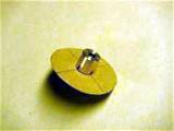
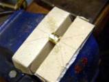
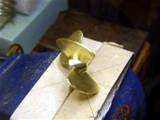
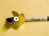
 Your finished product will look something like this "mess". When slightly
cooled, you can use rubbing alcohol and "q-tips" and a brass brush to clean
off most of the excess flux. Check the quality of the joints and retouch if
necessary, hopefully that's not needed; as that usually leads to less than
ideal results.
Your finished product will look something like this "mess". When slightly
cooled, you can use rubbing alcohol and "q-tips" and a brass brush to clean
off most of the excess flux. Check the quality of the joints and retouch if
necessary, hopefully that's not needed; as that usually leads to less than
ideal results.
 Finish the cleanup with Brasso or any other appropriate metal cleaner /
polish, you can coat with Varathane or lacquer if you want it to stay shiny.
Finish the cleanup with Brasso or any other appropriate metal cleaner /
polish, you can coat with Varathane or lacquer if you want it to stay shiny.
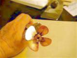
 Here are some other example propellers made using this technique with minor
variations in design of blades and hubs.
Here are some other example propellers made using this technique with minor
variations in design of blades and hubs.
I have used other variations of this technique over the years as well,
but this is my documentation of my technique for now.
Comments or suggestions for improvement (of the article) anyone?
Happy spinning!
Bob Warburton
|